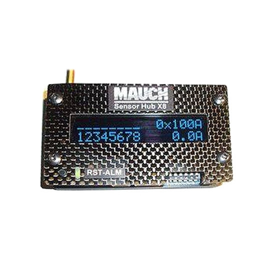
Every MAUCH product is manufactured and thoroughly bench tested using MAUCH’s rigorous process.

SENSOR HUB X8 TEST BENCH, INCLUDING PIXHAWK 2.1, POWER-CUBE AND 8X PC SENSORS
Mounting

The Sensor Hub X8 can be either installed via double side tape, or screwed down to the main frame, by removing the 4 bottom M3 screws and drilling holes into the frame. Then reinstall the screws trough the frame. -> The original screws will be too short, so please replace them with longer ones according your frame thickness.
Setup and Operating Description

SENSOR HUB X8 WIRING
1. Connection to Power-Cube:

CABLE PROVIDED WITH POWER-CUBE (NOT SENSOR HUB X8)
- Connect the “To P-C current sensor” cable from the Power-Cube to the Sensor Hub X8’s “To Power-Cube” connector (label 1 on the wiring diagram above).
- This connection carries the power supply for the Hub X8 as well as the connected current sensors.
- The voltage is 4.95-5.05V and the max. current should not exceed 0.5A. The current draw of the Hub X8 (with active OLED) is 50mA, plus 8x 15mA (current sensors) = 170mA (0.17A). With two Sensor Hub X8 and 16 current sensors, plus an Hub X2 (15mA), the current draw is still below the 0.5A.
(2 x 0.17A) + 0.015A = 0.335A.
2. Sensor connectors:

POWER-CUBE CURRENT SENSOR PC-200. (PC-100 ALSO COMPATIBLE)
Connect the PC-100 or PC-200 sensors to the sensor connectors (label 2). All sensors must have the same current rating.
If you use fewer than 8 sensors, the sensors can be connected to any sensor port.
For more details, please check item (9) below.
- The 8 cables to connect the PC sensor boards come together with the Hub X8 (L=200mm).
- Only PC-100 or PC-200 (Power-Cube) sensors can be used. The Hub X8 is not compatible with HS-xxx-xx sensors!

DISABLE UNUSED SENSORS BY DISCONNECTING THE GROUND WIRE
If all 8 possible sensors are installed, but you want to fly your UAV with only 4 LiPos, then you can deactivate the unused current sensors by either disconnecting them from the Hub X8, or installing a switch into the GND wire of the sensor board.
REM: Do not install the switch on the + 5V or I-out cable!
If the sensor is disconnected, or the GND wire is switched off, then the Hub X8 will deactivate the sensor input during boot up or restart.
3. Reset / Restart:
- re-powering the Hub X8; or
- pressing the reset switch for a short time.
If the reset switch is pressed longer than 2 seconds, then the Hub X8 will restart. This is helpful to deactivate installed sensors after switching on the system.
It is possible to install an external reset / restart switch (not included); the necessary 5p cable with connector is included with
2x red for external switch + 3x white for alarm relays output (label 5 on diagram).
4. Status LED:
GREEN = After boot up and all connected sensor are initialized / No active alarm.
5. Alarm Out:
- Pin 3 = P -> The middle contact of the relays.
- Pin 4 = NO (normal open).
- Pin 5 = NC (normal closed).
Any power LED or buzzer can be connected here, but the maximum current should not exceed 1A!
The necessary 5p cable with connector is included. -> 2x red for external switch + 3x white for alarm relays output.
6. External LCD / OLED display:

SENSOR HUB X8 WITH EXTERNAL OLED DISPLAY (NOT INCLUDED)
REM: External OLED displays with CFK cover and reset switch might be available soon. Please check item (7) below, for how to activate / deactivate the internal and external displays.
7. Setup DIP switch:
OFF OFF Internal and external display OFF
OFF ON Internal display ON / External display OFF
ON OFF Internal display OFF / External display ON
ON ON Internal and external display ON
ON OFF OFF OFF 50A Sensors (PC-050 Sensors coming soon)
ON ON OFF OFF 100A Sensors
ON ON ON OFF 200A Sensors
ON ON ON ON 400A Sensors (PC-400 Sensors are expected to be available at the end of 2017)
8. I2C connector:

9. Sensor status indicator:
II = Sensor connected and current is close to average of the other measured currents.
L = The current of this sensor is at least 25% lower than the average current of the other sensors -> Alarm relay active.
H = The current of this sensor is at least 25% higher than the average current of the other sensors -> Alarm relay active.
10. Sensor indicator:
11. Current display:
12. Current output and setup Mission Planner:
- 4 x 100A Sensors = 0.0V @ 0A and 3.3V @ 400A -> Amp/Volt value = 120
- 5 x 200A Sensors = 0.0V @ 0A and 3.3V @ 1000A -> Amp/Volt value = 300
- 8 x 200A Sensors = 0.0V @ 0A and 3.3V @ 1600A -> Amp/Volt value = 480

AMP/VOLT VALUES FOR SENSOR CURRENT RATING (LEFT) AND NUMBER OF SENSORS (TOP)

![DJI Mini 3 Pro [image]](https://www.onedrone.com/store/image/cache/catalog/banners/dji_mini_3_pro_no_rc_-550x550w-200x120w.jpg)


-150x150h.jpg)





-1000x1000-150x150.jpg)



-150x150.png)


